1 WHAT IS AU PIC18F SERIAL BOOTLOADER?
Au PIC18F Serial Bootloaders are low cost yet high reliable solutions for upgrading PIC18F Microcontroller (MCU) firmware via RS232 interfaces. They are suitable for any target boards/products equipped with Microchip® PIC18F microcontrollers and RS232 interfaces.
With the Au PIC18F bootloader program embedded in the PIC18F MCU, new application firmware code can be upgraded into PIC18F MCU in-field without bringing the device back to manufacturer’s facility. The application firmware code is downloaded via a PC RS232 interface. So there is no need to open/damage products original package/enclosure.
2 TWO SOLUTIONS
There are two solutions available for Au PIC18F serial bootloader: non-encrypted solution and encrypted solution.
• Non-encrypted solution uses regular "Hex" format files for firmware upgrade; it can be used for products with no requirements of intellectual property (IP) protection.
• Encrypted solution uses encrypted algorithm in a proprietary "Aud" format to prevent the PIC18F firmware from directly exposure to third parties. The unique dynamic encryption algorithm makes firmware-hack mission impossible. The encryption feature helps preventing the firmware intellectual property from being copied/miss-used by un-authorized third parties.
With Au Group Electronics developed encryption technology, for any encrypted solution:
1. Each encrypted firmware code (*.aud file) is unique;
2. Each encrypted firmware code (*.aud file) is traceable with a unique digital watermark;
3. Each firmware-downloading process is unique.
All these three features provide a good protection of Intellectual Property (IP).
MCU resources used for both solutions are listed in Table 1-1. Please note, EEPROM is reserved for software trigger feature.

Au Group Electronics is proud to announce the following Au Group Electronics developed products are maintained and protected by PIC18F Encrypted Serial Bootloader: six editions of J1939 Simulators, J1939 Data Centers, J1939 Message Centers, J1939 Interpreters, etc. Au Group Electronics also provide/design other PIC family bootloaders with or without encryption features, e.g. dsPIC30Fs, dsPIC33Fs, etc.
In this user manual, we will use Au J1939 Simulator Gen II as an example to demonstrate how easy an Au PIC18F Serial Bootloader can be applied to a product (Chapter 1.7).
Note: Microchip, PIC18F, PICkit 2, and ICD2 are trademark of Microchip Inc.
3 MAJOR FEATURES OF AU PIC18F SERIAL BOOTLOADER
The following features have been tested and used in-field and are listed here:
• High Reliability
• High level of Security
• Low cost
• Turn key solution and full support
• Great flexibility: Custom design available, e.g. encrypted and non-encrypted solutions; different oscillator frequencies, 20M Hz, 16M Hz, etc.; different communication baud Rate: 115.2K, 57.6K, etc.
Au PIC18F serial bootloader is also been considered as a "Green" product for the following features:
• No need to take the circuit board out of the enclosure. So the product package won’t be damaged. (Save material and time)
• No extra programming tool or software needed. (Save tooling cost)
• No need to send final products to original manufacturer. (Save shipping cost and time)
• No more long waiting period (e.g. days, weeks) while product is being upgraded. It only takes from a few seconds to a few minutes to upgrade the product. (Save time)
4 WHAT'S NEEDED TO USE AU PIC18F SERIAL BOOTLOADER?
Following items are needed to use Au bootload firmware with a PIC18F MCU:
1. Customer application hardware (e.g. circuit board, devices, etc.) with PIC18F microcontroller and RS232 interface
2. Customer application software (in hex format or aud format)
3. Bootloader hex code: e.g. an Au PIC18F4580 Bootloader
4. MCU programmer: e.g. Au BB0703 (PICkit 2) family products
5. RS232 extension cable: connect to RS232 port on PC
6. USB cable: to connect a PC to MCU programmer (BB0703)
7. USB to RS232 converter: optional, it is only needed for PC only equipped with USB ports
Note: Due to the fact, few serial ports are available in modern computers, Au PIC18F serial bootloader is designed to be compatible with most popular USB to RS232 converters. All Au PIC18F serial bootloader products have been rigorously tested with regular PC serial ports and USB to RS232 converters.
8. PC with RS232 port and USB port. Also the following software are needed:
a. Au PIC18F Serial Bootloader PC side application software
b. PIC Programmer PC side software: e.g. PICKit 2 Programmer
c. Microcontroller development software: e.g. MPLAB IDE, MCU C compiler
d. Hex encryption PC side software: Au HexEncoder (Optional)
Item 1, 2, 4, 5, 6, 7 are customer provided or designed items. Item 3, 8-a, 8-d are provided by Au Group Electronics. Item 8-b and 8-c are available from Microchip or MCU Compiler vendors.
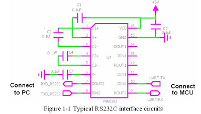
5 RECOMMENDATION OF SERIAL INTERFACE CIRCUITS DESIGN
The following diagram (Figure 1-1) illustrates a typical RS232C interface circuit for application design.

6 INFORMATION NEEDED FROM CUSTOMER
To get custom designed PIC18F bootloader started, the following information is needed:
1. Particular PIC18F controller model, package
2. Microcontroller oscillator frequency
3. Microcontroller oscillator mode
4. Bootloader hardware trigger pin assignment
5. Bootloader mode LED assignment
6. Other special configuration bits requirements
7. Optional software bootloader entry trigger feature: If software bootloader entry trigger feature is needed, more application memory space will be needed. This also requires some customer program for the integration.
7 ITEMS CUSTOMER WILL RECEIVE
1. A CD includes the following items:
a. Au PIC18F bootloader hex code (*.hex).
b. A PC installation program for Au PIC bootloader application software
c. Hex Encoder (optional): a PC installation program for hex encryption. This item is only provided with the purchase of an encrypted bootloader solution.
2. User manual for Au PIC18F Serial Bootloader
8 APPLICATION EXAMPLE
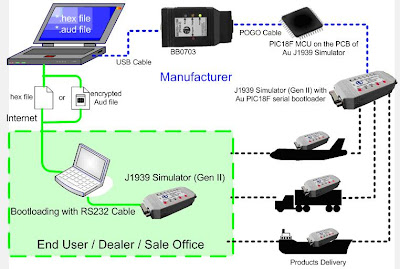
Now, we will outline the procedure of how the Au PIC18F Serial Bootloader is applied in one of our products – Au J1939 Simulator (Gen II). The whole procedure is summarized in Figure 1-2.
1. At the manufacturer facility, PIC18F Serial Bootloader hex file is merged with the J1939 Simulator Application hex file.
2. Target chipset (PIC18F MCU) is soldered on PCB, 6 ICSP (In-Circuit Serial Programming) pads are available on PCB
3. Connect PC with programmer (BB0703) through a USB cable.
4. Connect BB0703 with the target board through an Au POGO cable.
5. Merged hex file was first burned in the target PIC18F MCU by BB0703 through the POGO cable and the USB cable before the circuit board is installed into the enclosure.
6. Assemble all other components and package them into an enclosure.
7. Final products are delivered to end user/dealer/sales office
8. When new J1939 Simulator application software (firmware) needs to be upgraded, Au Group Electronics sends encrypted "aud" file to end-user/dealer/sale office by email, software disc, USB thumb drive, or FTP, etc.
9. The end-user/dealer/sales connects J1939 Simulator to a PC with a RS232 cable, then the aud file can be downloaded into PIC18F chip in-field, so the new feature is ready in a very short time (ranging from a few seconds to a few minutes).

Figure 1-2 Product lifetime firmware management with Au PIC18F Serial Bootloader
This is a simlified edition of Au PIC18F Serial Bootloader User Manual, for detail information about how to merge your application software with Au Group Electronics developed PIC18F bootloader, please contact us at support@auelectronics.com

No comments:
Post a Comment
Any comments, suggestion, idea? Please posted here.