Search this Blog

Friday, January 30, 2009

How to calibrate BB0703(Enhanced PICkit 2)?

Author: Chaonan Chen, Au Group Electronics
Following steps showing you how to calibrate the PICkit 2:
1. Double click the shortcut of PICkit 2 on desktop as shown in figure 1
2. PICkit 2 Programmer window show up (figure 2) and showing message “PICkit 2 not found. Check USB connections and use ToolsàCheck Communication to retry”
3. Connect PICkit 2 with computer using appropriate USB cable, the power LED on PICkit 2 will lit as shown in figure 3.
4. Click Tools/Check Communication on PICkit 2 programmer windows, as shown in figure 4, the programmer will then show message “PICkit 2 found and connected”

5. Click Tools/Calibrate VDD & Set Unit ID, as shown in figure 5.
6. “PICkit 2 VDD Calibration” window show up, click next to proceed (figure 6)
PICkit 2 VDD calibration window will show with the 3 steps (figure 7)
Step 1. Make sure the PICkit 2 is not connected to any device or circuit board.
Step 2. Connect a voltage meter between pin 2 (VDD) and pin 3 (GND) of the CB0703 (PICkit 2) ICSP connector (the pin number is defined as shown in figure 8). The voltage meter showing at 0.2mV (figure 9).
Step 3. Click NEXT and PICkit 2 will apply approximately 4 volts to the VDD pin.
Step 4. Connect a voltage meter between pin 2 (VDD) and pin 3 (GND) of the PICkit 2 ICSP connector again, the reading on the volt meter is the actual voltage measured on VDD (figure 10). Enter the value in the box as shown in figure11.
Step 5. Click the CALIBRATE button to calibrate the PICkit 2. “CALIBRATION SUCCESSFUL” message displayed. Click “Next” to proceed (figure 12).
7. “Unit Identification Name” window show up, type “MYPICKIT2” or any other name and click “Assign Unit ID” button, message “Unit ID Assigned to this PICkit 2” displayed. Click “Finished” button (figure 13).
8. PICkit 2 Programmer – MYPICKIT 2 window show up, and a message “PICkit 2 connected. ID = MYPICKIT 2” display (figure 14).

Thursday, January 22, 2009

How to place order online at Au Group Electronics?

Author: Chaonan Chen, Au Group Electronics
Thanks for choosing products from Au Group Electronics. Order online is fast, secure and convenient.
1. Click "Add to Cart" icon on any product from our website: www.AuElectronics.com.
2. Click “Continue Shopping” icon, as shown in figure 1, a question window may display (figure 2), click "Yes" to get back to original webpage for selecting other products
3. Click "Proceed to Checkout" after finishing shopping (as shown in figure 3).
4. If summarized items display (figure 4), click the down arrow to view detail description on the ordered items, the down arrow will turn to up arrow (figure 5), click the up arrow, detail information will be hidden again.
5. Click “Continue” for payment option.
6. Two major payments are acceptable: PayPal or credit cards (figure 7)
• For PayPal user, use the form on the right side to log in, then follow step 7 to 8 for PayPal payment instruction.
• For payment with credit card, use the form on the left side, then follow step 9 for credit card payment instruction.
7. For payment with PayPal, enter the email address of your PayPal account and password in the window on the right side, then click “Log in” button, as shown in figure 8.
8. Review your order and payment information, if the information is correct, click "Pay Now" button to complete your order, as shown in figure 9
9. For payment with credit card, enter all necessary information, then click “Review Order and Continue” button, as shown in figure 10.
Note: make sure the billing address is entered correctly. Otherwise the payment may not be able to go through. It is the address for your credit card. It may not be the same as the shipping address
10. After inputting and reviewing all your payment information: Item purchased, payment method, shipping address, and contact information etc., click “Pay Now” button to confirm order.

Tuesday, January 20, 2009

How to trouble shoot PICkit 2?

Author: Huihui Duan, Chaonan Chen, Au Group Electronics
To trouble shoot a PICkit2, a multimeter, a frequency measurement tool and a oscilloscope might be needed.

The tool showed in this article is a Craftman Auto-ranging multimeter 82139, which has a voltmeter function and a frequency counter function. It can also measurement the signal high level percentage of a square ware. The multimeter 82139 is available at local Sears stores.

1. After launch the "PICKit 2 programmer" software, Click "Tools/Troubleshoot" as shown in figure 1.

Figure 1

2."PICkit 2 troubleshooting" windows displays, click "Next" (figure 2)

3."PICkit 2 Troubleshooting Step 1: Verify VDD" window shows up (figure 3):

4.Verify VDD

4.1.Type "4.5", click "Test" button, PICkit 2 Troubleshooting window will display "Results 4.4V" and a "Test Passed" message (figure 4-1).

You can also verify the voltage by using volt meter to measure the voltage of VDD (pin2 +, pin3 - ) at 4.49V (figure 4-2).

4.2.Type "2.5", click "Test" button, "Results 2.5V" displays, volt meter reads VDD (pin2 +, pin3 -), at 2.506V (figure 4-3).
4.3.Type "3.3", click "Test" button, "Results 3.3V" displays, volt meter reads VDD (pin2 +, pin3 -), at 3.325V (figure 4-4). Click Next to test VPP. Note: The last test value of VDD will affect the test result of PGC and PGD on step 6.
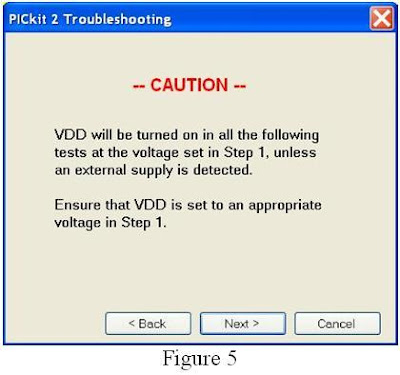
4.4."PICkit 2 Trouble shooting CAUTION" window displays (figure 5), click "Next", "PICkit 2 Troubleshooting Step 2: Verify VPP" window displays (figure 6)
5.Verify VPP

5.1.Click "Test VPP" button, VPP test result displays "11.9 V", and a "Test Passed" message displayed (figure 7-1).
You can also use volt meter reads VPP (pin 1+, pin 3-) at 11.91V (figure 7-2)

5.2.Click "MCLR On" button, volt meter measures (Pin1 +, pin 3- ) at a few mV (Figure 8-1 shows 6.5 mV).
5.3.Click "MCLR Off" button, volt meter measures (Pin1 +, pin 3- ) at an indeterminate voltage (figure 8-2 shows about 36.2 mV). Click "Next"
6.Verify PGC + PGD

6.1."PICkit 2 Troubleshooting/Step 3: Verify PGC + PGD" window displays (figure 9)

6.2.Under PGD/ICSPDAT:

6.2.1.Click “Toggle 30KHz” button, , the frequency should read about 29.91 kHz (pin 4 + Pin 3-, figure 10-1), frequency % reads about 45.2% (figure 10-2), voltage reads about 1.724V (figure 10-3)
6.2.2. Click “High (VDD)” button, volt meter reads the voltage at 3.317 volt (figure 10-4),
Note: these voltage values (figure 10-3 and 10-4) maybe different depends on the last test value of VDD (see step 4).
6.2.3. Click “Low (GND)” button, volt meter reads the voltage at a few mV (picture not shown).

6.3.Under PGC/ICSPCLK:

6.3.1. Click “Toggle 30KHz” button, the frequency should read about 29.91 kHz (pin 5 + Pin 3-, figure 11-1), frequency % reads about 45.4% (figure 11-2), voltage reads about 1.73V (figure 11-3) 6.3.2. Click “High (VDD)” button, volt meter reads the voltage at 3.309 volt (figure 11-4).
Note: these voltage values (figure 11-3 and 11-4) maybe different depends on the last test value of VDD (see step 4).
6.3.3. Click “Low (GND)” button, volt meter reads the voltage at a few mV (picture not shown).

7.Click "Finished" button to close PICkit 2 Troubleshooting window.

How to Program PICs (DIP) with Breadboard?

Author: Huihui Duan, Chaonan Chen, Au Group Electronics
There are many different approaches to program the DIP (Dual In-Line) PIC chips without very expensive programming fixtures.
This document provides one of the many possible solutions for Microchip PIC fans and Engineering students. It illustrates step by step instructions on how to use the AU Group Electronics BB0703 (PICkit2) and breadboard for downloading programs into the DIP PIC chips.
What you need:
How to connect the target PIC chip to PC for programming:
As illustrated in figure 1, by using USB cable, RJ12 6-pin reverse cable, and RJ12 programming extension cable, the target chip can be connected to your PC through BB0703 (PICkit 2).

Note: Make sure using the exact parts as described in figure 1. Otherwise, ICSP (In-Circuit Serial Programming) signal sequence on programming cable might be different than table 1 illustrated.
Signal definition of RJ12 programming extension cable on figure 1
As shown in figure 1, the signal of each color wire of RJ12 programming extension cable is listed in table 1:
Pin Number/Signal Identification of Target PIC Chips:
The following figures show two examples of ICSP pins on two DIP microcontrollers: a PIC12F508-I/P and a PIC18F4550-I/P. For any other type of chips, please refer to related Microchip Data Sheet.
PIC12F508-I/P
For PIC12F508-I/P, pin 1, 4, 6, 7, and 8 will be used for ICSP programming, these pins are highlighted with the same wire color of RJ12 programming extension cable, as shown in figure 2.

PIC18F4550-I/P

Figure 3 PIC18F4550 Pins/Signals Identification

Step by Step connections:

  1. Insert a target DIP PIC chip to breadboard.
  2. Inset the 5 wires of RJ12 programming extension cable to respective position of the breadboard where the above 5 ICSP-programming-pins seated.
  3. Using USB cable to connect BB0703 (PICkit 2) with PC.
  4. Using RJ12 6 pin Reverse cable (Au Group Electronics part # CBL-RJ12-RVS) to connect RJ12 programming extension cable and BB0703 (PICkit 2).
  5. Program the target chip with PC application software: MPLAB IDE or PICkit 2 programmer. (step by step operation is illustrated in next chapter.)
  6. After target chip is programmed, disconnect “RJ12 programming extension cable” and BB0703 (PICkit 2) by removing one end of the “RJ12 6Pin reverse cable” on either side first, then, take the programmed-chip off the breadboard.
  7. If more chips need be programmed, repeat above step from 4 to 6 after new chip is inserted into the breadboard.

Figure 4 Demo connections with breadboard (using PIC18F4550)

Programming with PICkit 2 Programmer or MPLAB IDE
After the target chip is connected as figure 4 shows, you may program the chip through one of the following application software: by using PICkit 2 Programmer or by using MPLAB IDE.
Using PICkit 2 Programmer

1. Double click shortcut “PICkit 2 programmer” on desktop, as shown in figure 5.

2. "PICkit 2 Programmer” window shows up, select PIC12F508 from the device drop down list, as shown in figure 6.

Figure 6 PICkit 2 Programmer window
3. Click “File/Import Hex” to load hex file, as shown in figure 7.
Figure 7 Import Hex file
4. Click “Write” button, the selected hex file will be programmed into the target chip, and “Programming Successful” message will display, as shown in figure 8.
Figure 8 Programming Successfully
5. If more chips will be programmed, repeat 1-4 after a new blank-chip is installed as shown in figure 4. If same hex is used, you don’t need re-load the hex file.
Using MPLAB IDE software
1. Double click shortcut “MPLAB IDE” on desktop, as shown in figure 9.
Figure 9 MPLAB IDE shortcut
2. Click “Configure/Select Device…”, “Select Device” window opens up, select “PIC18F4550” from the device drop down list, then click “OK”, as shown in figure 10. PIC18F4550 will show up in the bottom status bar (not shown here in any pictures).
Figure 10 Select Device
3. Click “File/Import…” to open a xxx.hex file, the output window will show a hex file loaded, as shown in figure 11
Figure 11 Load hex file
4. Check the configuration Bits from: Configure/Configuration Bits…. Make changes if necessary.
Figure 12 Verify Configuration Bit
5. Click “Programmer/Select Programmer/PICkit 2”, as shown in figure 13.
Figure 13 Select Program Device
6. PICkit 2 will initialize and a message “PICkit 2 Ready” will show up, as shown in figure 14.
Note: the message in the green frame may not display, it depends if there is a newer version of PICkit 2 operating system or not. Whenever there is a newer version available, it will be downloaded automatically by default. (The red highlighted icon is the programming icon.)
Figure 14 PICkit 2 is connected and ready
7. Click program icon, the hex file will be burned into the target chip. And similar message as shown in the blue frame will be displayed (see figure 15).
Figure 15
Note: After the chip is programmed, please disconnect the "RJ12 programming extension cable" and the "BB0703 (PICkit2)" by removing one end of the “RJ12 6Pin reverse cable” first, then, take the programmed chip off the breadboard.
If there are more chips to be programmed, please repeat steps 1-7 after the chip is inserted into the breadboard. Also you don’t need re-load the hex file if the same hex is used.

Sunday, January 18, 2009

How to Configure modem and Router for Web Servers

Configure WESTELL DSL 6100 modem and Netgear WGT624 V3 Router for Small Business Web / Ftp / Email Servers
Author: Huihui Duan, Chaonan Chen, Au Group Electronics
Jan 16, 2009
Welland, ON, Canada
Hosting a Web / Ftp / Email server in-house is a low cost solution for small business owners. Comparing with third party web host, in-house internet server provides some advantages:
  • Relative low cost
  • Sufficient bandwidth and unlimited traffic
  • Real time traffic monitoring
  • Secure and fast response to unexpected events
DSL high speed internet service is widely available in USA, Canada and many part of the world. And it provides enough bandwidth for small business Web / Ftp / Email servers.

To forward all internet requests to a Web / Ftp / Email server, it is required to configure the DSL modem and router correctly. It relates to NAT (Network address translation) and port forwarding technology. A Westell 6100 DSL modem and a Netgear WGT624 V3 Router are used in the document for demonstration purpose (Figure 1).

Figure 1 Network Layout for in-house Web / Ftp / Email server

Change Router LAN IP setup

Both Westell 6100 DSL modem and Netgear WGT624 V3 Router have a default LAN IP address of 192.168.1.1. It is recommended to change one of the device IP address to 192.168.2.1. On this document, the Netgear WGT624 V3 Router address is changed to 192.168.2.1. (Figure 2)

After log on into the router control panel by typing 192.168.1.1, select "LAN IP Setup", and change the IP address to 192.168.2.1 (Figure 2.)

Figure 2 Change WGT624 V3 Router IP address to 192.168.2.1

Configure Westell DSL 6100 modem
Open a windows internet explorer, type 192.168.1.1 in the address bar.

Figure 3 IP address of Westell DSL 6100 modem

The connection overview window will display.

Figure 4 Connection Overview of DSL Modem

Under the configuration menu, there are following 11 configurations: VC configuration, DNS Configuration, DHCP Configuration, Private LAN Configuration, Public LAN Configuration, Detect WAN Configuration, Single Static IP Configuration, Service Configuration, Firewall Configuration, ATM Loopbacks, Turbo TCP, as shown in figure 5


Figure 5 List of Configuration Menu

Verify that all the 11 configurations are set up as following:

Figure 6 VC configuration

Figure 7 DNS configuration

Figure 8 DHCP Configuration

Figure 9 Private LAN Configuration
Figure 10 Public LAN Configuration

Figure 11 Detect WAN Configuration

On single static IP configuration please select "enable", after it is enabled, it reads as figure 12.
Figure 12 Single Static IP Configuration

Please make sure there are no other service enabled and no static NAT as shown in Figure 13.
Figure 13 Service Configuration

Select "None" on Firewall Configuration (Figure 14). Figure 14 Firewall Configuration
Figure 15 ATM Loopback
Figure 16 Turbo TCP

Configure Netgear WGT624 V3
3.1.Type 192.168.2.1 in the address bar to enter into Netgear server

Figure 17 IP address for Netgear WGT624 V3 Setting

3.2.Enter username and password to enter Netgear WGT624 V3 Configure Setting, as shown in figure 18.

Figure 18 Log into Netgear Setting

3.3.Click the "Port Forwarding/Port Triggering" at the setup wizard on left hand side, make sure the service type "Port Forwarding" is selected, then click "Add Custom Service", as shown in figure 19. Figure 19 Port Forwarding/Port Triggering

3.4.Add a Web server service per the following setting as shown in figure 20. Make sure port 80 is used for Web server, and server IP address set at 192.168.2.2, then click "Apply".

Figure 20 Add a new custom Service – Web server

3.5.Web server service port forwarding is setup, notice that the new service named "Web” is added to the service list, as shown in figure 21, item #3.

Figure 21 Web Server Port Forwarding

3.6. Follow the same procedure from step 3.3 to 3.5 for setting up FTP server and Email server. Please note that port # for FTP server and Email server are different then web server. Please refer to figure 1 for correct port selection.