Author: Chaonan Chen, Huihui Duan, Au Group Electronics
This application note use a dsPIC30F2010 (28-pin SDIP package) demonstrate step by step operation on how to use Au Group Electronics "3-in-1 mini-Lab" and "BB0703" to burn program/code into the dsPIC30F microcontroller.
What you need:
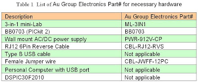
Major devices that were used in this application note and their Au Group Electronics part # are listed in table 1.
There are two methods to load hex file into target chipset: programming with a PC or Programmer-to-Go. This application note will show both methods.
Program dsPIC30F2010 with a PC:
If hex file has not been burned into BB003 (PICkit 2) programmer, a PC is needed. The hardware setup of Programming with a PC would be similar like figure 1.
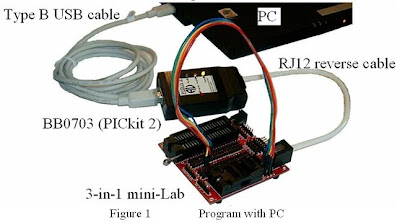
Step 1. Connect 3-in-1 mini-lab, BB0703 with a PC by RJ12 6Pin reverse cable and type B USB cable.
Step 2. Place a piece of dsPIC30F2010 into the 3-in-1 mini-Lab DIP ZIF socket
Note: Only place one chip at a time. E.g. either put a SOIC packaged chipset in SOIC-ZIF socket; or put a DIP packaged chipset in DIP-ZIF socket. Make sure Pin 1 of dsPIC30F2010 agrees with the 1st-pin-mark on circuit board.
Step 3. Use 9 pieces of female jumper wires to connect J1-x to JZ-x on 3-in-1 mini Lab. The position of both ends of the female jump wires are color coded in Table 2.
Note: J1 (J1-1, J1-2, J1-3) are the extension pin headers for RJ12 6P6C connector
JZ-x (JZ-1 to JZ-6) are the extension pin headers for SOIC and DIP ZIF socket.
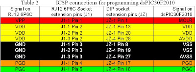
ICSP signal on J1 and dsPIC30F2010 are illustrated in figure 2 for reference

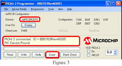
Step 4. Double click shortcut of “PICKit 2 V2.6” to open a "PICkit 2 Programmer", Make sure “PICkit 2 connected, and it’s displayed in the message window, and PIC Device (dsPIC30F2010) found, as shown in figure 3.
If the device in the ZIF socket are not auto-detect, Click ProgrammerManual Device Select, make sure the checkmark before "Manual Device Select" is gone (picture not show).
Step 5. Click “Erase” button, as shown in figure 3. Wait a few seconds until “Erasing device … Complete”.
Step 6. Click “Blank Check” button, as shown in figure 4.
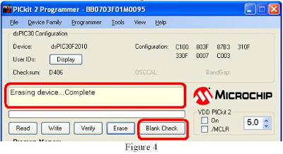
Wait a few seconds, “Device is Blank” will display, as shown in figure 5
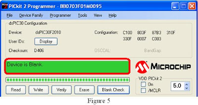
Step 7. Load the hex file, then click “Write” button, as shown in figure 6.
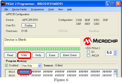
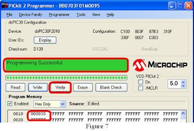
Wait a few seconds, message box will display "Programming Successful", as shown in figure 7
For programming multiple chipsets, Programmer-to-Go will be another convenient and productive solution. It will be demonstrated at the following steps.
Programmer-to-Go (Programming without a PC)
Step 1. Refer to BB0703 (PICkit 2) PTG application note for how to import and download hex file into BB0703 (PICkit 2). After that, PC is not needed for programming microcontroller.
Step 2. Connect the BB0703 with 3-in-1 mini-Lab using a RJ12 reverse cable.
Step 3. Power up BB0703 with +9 V DC supply, as shown in figure 8. The "Target" LED will blink indicating it's ready to program target chip.
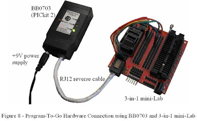
Step 4. Load dsPIC30F2010 into ZIF socket.
Step 5. Press "Program" button on BB0703 (PICkit 2), "Busy" LED will be constant on,
Step 6. Wait a few seconds/minutes, until "Busy" LED is off and "Target" LED blink again, which means the hex file has been burned into the target chipset successfully.
Step 7. Repeat steps 4-6 for programming another dsPIC30F2010 chipset

No comments:
Post a Comment
Any comments, suggestion, idea? Please posted here.