Friday, March 20, 2009
3-in-1 mini-Lab Application Note for dsPIC30F2010
Author: Chaonan Chen, Huihui Duan, Au Group Electronics
This application note use a dsPIC30F2010 (28-pin SDIP package) demonstrate step by step operation on how to use Au Group Electronics "3-in-1 mini-Lab" and "BB0703" to burn program/code into the dsPIC30F microcontroller.
What you need:
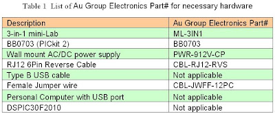
Major devices that were used in this application note and their Au Group Electronics part # are listed in table 1.
There are two methods to load hex file into target chipset: programming with a PC or Programmer-to-Go. This application note will show both methods.
Program dsPIC30F2010 with a PC:
If hex file has not been burned into BB003 (PICkit 2) programmer, a PC is needed. The hardware setup of Programming with a PC would be similar like figure 1.
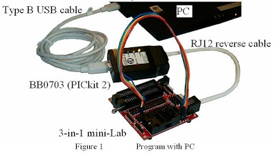
Step 1. Connect 3-in-1 mini-lab, BB0703 with a PC by RJ12 6Pin reverse cable and type B USB cable.
Step 2. Place a piece of dsPIC30F2010 into the 3-in-1 mini-Lab DIP ZIF socket
Note: Only place one chip at a time. E.g. either put a SOIC packaged chipset in SOIC-ZIF socket; or put a DIP packaged chipset in DIP-ZIF socket. Make sure Pin 1 of dsPIC30F2010 agrees with the 1st-pin-mark on circuit board.
Step 3. Use 9 pieces of female jumper wires to connect J1-x to JZ-x on 3-in-1 mini Lab. The position of both ends of the female jump wires are color coded in Table 2.
Note: J1 (J1-1, J1-2, J1-3) are the extension pin headers for RJ12 6P6C connector
JZ-x (JZ-1 to JZ-6) are the extension pin headers for SOIC and DIP ZIF socket.
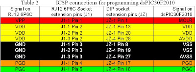
ICSP signal on J1 and dsPIC30F2010 are illustrated in figure 2 for reference
Step 4. Double click shortcut of “PICKit 2 V2.6” to open a "PICkit 2 Programmer", Make sure “PICkit 2 connected, and it’s displayed in the message window, and PIC Device (dsPIC30F2010) found, as shown in figure 3.
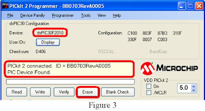
If the device in the ZIF socket are not auto-detect, Click ProgrammerManual Device Select, make sure the checkmark before "Manual Device Select" is gone (picture not show).
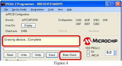
Step 5. Click “Erase” button, as shown in figure 3. Wait a few seconds until “Erasing device … Complete”.
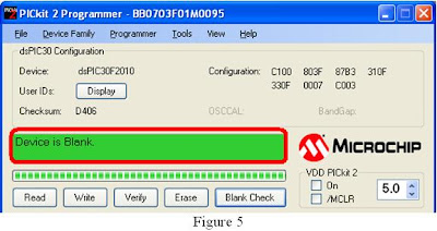
Step 6. Click “Blank Check” button, as shown in figure 4.
Wait a few seconds, “Device is Blank” will display, as shown in figure 5
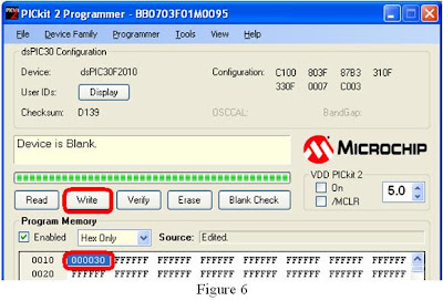
Step 7. Load the hex file, then click “Write” button, as shown in figure 6.
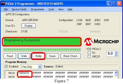
Wait a few seconds, message box will display "Programming Successful", as shown in figure 7
For programming multiple chipsets, Programmer-to-Go will be another convenient and productive solution. It will be demonstrated at the following steps.
Programmer-to-Go (Programming without a PC)
Step 1. Refer to BB0703 (PICkit 2) PTG application note for how to import and download hex file into BB0703 (PICkit 2). After that, PC is not needed for programming microcontroller.
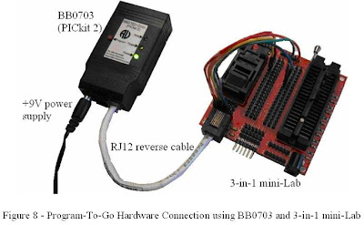
Step 2. Connect the BB0703 with 3-in-1 mini-Lab using a RJ12 reverse cable.
Step 3. Power up BB0703 with +9 V DC supply, as shown in figure 8. The "Target" LED will blink indicating it's ready to program target chip.
Step 4. Load dsPIC30F2010 into ZIF socket.
Step 5. Press "Program" button on BB0703 (PICkit 2), "Busy" LED will be constant on,
Step 6. Wait a few seconds/minutes, until "Busy" LED is off and "Target" LED blink again, which means the hex file has been burned into the target chipset successfully.
Step 7. Repeat steps 4-6 for programming another dsPIC30F2010 chipset
Thursday, March 19, 2009
3-in-1 mini-Lab Application Note for dsPIC33FJ64GP802
Au Group Electronics
Author: Chaonan Chen, Huihui Duan, Au Group Electronics
This application note uses a dsPIC33FJ64GP802 (28-pin SOIC SMD package) demonstrating step by step operation on how to use Au Group Electronics "3-in-1 mini-Lab" and "BB0703 programmer" to burn program/code into a dsPIC33F microcontroller.
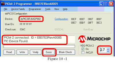
(Note: Experiences found that the VDD level on BB0703 (PICkit 2) is very critical for programming dsPIC33F family microcontrollers, without set it correctly might result in program/erase/blank-check failure. Due to design/engineering tolerance, it is noticeable that the actual VDD voltage on each individual BB0703 (PICkit 2) devices can vary up to 0.1V while programming.)
What you need:
Program dsPIC33FJ64GP with a PC:
Note: J1 (J1-1, J1-2, J1-3) are the extension pin headers for RJ12 6P6C connector
JZ-x (JZ-1 to JZ-6) are the extension pin headers for SOIC and DIP ZIF socket.
ICSP signal on J1 and dsPIC33FJ64GP802 are illustrated in figure 3 for reference
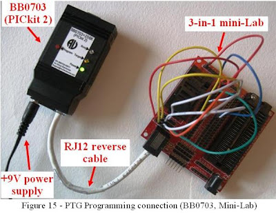
The hardware setup of Programming with a PC is shown in figure 4.
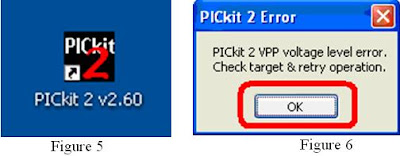
Step 4. Double click shortcut of “PICKit 2 V2.6” (Figure 5)
Step 5. A PICkit 2 Error message may or maynot show up (figure 6). Click “Ok” button. "PICkit 2 Programmer" window open up, PICkit 2 connected and ID displayed but No Device Found, as shown in figure 7.
All the jump wire connection on 3-in-1 mini-Lab and the signal on both ends are summarized in table 2
Step 7. On PICkit 2 programmer software interface, Click Tools/Check Communication (figure 9).
Step 8. Notice that PIC Device found, and dsPIC33FJ64GP802 displayed. Lower VDD from 3.3 to lower range (between 2.7V to 2.9V)*, and check VDD On, then click “Erase” button (figure 10-1).
If the device in the ZIF socket are not auto-detect, Click "Programmer->Manual Device Select", make sure the checkmark before "Manual Device Select" is gone (picture not show).
Wait a few seconds, “Device is Blank” will display, as shown in figure 12
Step 10. Load your target Hex file, then click “Write” button, as shown in figure 13.
Wait a few seconds, message box will display "Programming Successful", as shown in figure 14
For programming multiple chipsets, the Programmer-to-Go feature on BB0703 (PICkit 2) will be another convenient and productive solution. It will be demonstrated at the following steps.
Programmer-to-Go (Programming without a PC)
Attachment:
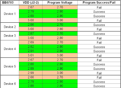
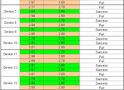
Test Result to Find the user friendly VDD zone for dsPIC33F64GP802
(Note: Test Data for technical reference only, it cannot be used for any other purpose.)
(VDD: voltage measured at chip end)
(Program Voltage: VDD set by PICKit 2 application sofware)
Thursday, March 5, 2009
3-in-1 mini-Lab Application Note for PIC16F628A
Au Group Electronics developed 2-in-1 mini-Lab or 3-in-1 mini-Lab is an integrated system capable of programming and on-board testing PIC microcontroller in both SOIC (up to 28 pin) and DIP (DIP 8, 14, 18, 20, 28, 40) packaging. It is able to connect microcontrollers to multiple programmers (e.g. Au Group Electronics BB0703, BB0703+, microchip PICkit2, ICD2, ICD3, RealICE, etc.) through either a "6-pin ICSP header" or a "RJ12 6P6C socket". It also provides lab-test circuits including on-board voltage regulator (+5V, +3.3V, +2.5V), pull-up circuit, pull-down circuit, cap connection, bidirectional voltage-level translator, and LEDs.
This application notes will demonstrate:
1. ICSP wire connection
2. Step by step Hex programming for PIC16F628A in DIP/SOIC packaging
3. On-board LED test with 6-digit binary LED counter program.
What you need:
All hardware that were used in this application note are listed in table 1.
To burn program into microcontroller, the 6 ICSP connections need to be build between the RJ12 6P6C connector (J1) and the target chipset. On 3-in-1 mini-lab, J1-1, J1-2, J1-3 are the extension pin headers for RJ12 6P6C connector, JZ-x (JZ-1 to JZ-6) are the extension pin headers for SOIC and DIP ZIF socket. The 5 ICSP signal on a few microcontrollers are illustrated in figure 2. Use female jumper wires to connect J1-1 to JZ-x per table 3. The connection is demonstrated in figure 3. There are two methods to load hex file into target chipset: programming with a PC or Programmer-to-Go.
Programming with a PC
1. Place one piece of PIC16F628A chipset into the DIP/SOIC ZIF socket of the 3-in-1 mini-Lab (Note: only place one PIC chip at a time. E.g. put a SOIC packaged chipset in SOIC-ZIF socket; or put a DIP packaged chipset in DIP-ZIF socket. Please make sure Pin 1 of PIC16F628A agrees with the 1st-pin-mark on the circuit board)
2. Connect 3-in-1 mini-Lab, BB0703, and a PC by using a "RJ12 6Pin reverse cable" and a "type-B USB cable", as shown in figure 4.
3. Double click PICkit 2 shortcut icon on desktop to open up PICkit 2 Programmer window.
4. "PICkit 2 Programmer" window open up. If device name "PIC16F628A" and "Midrange / Standard Device found" displayed, as shown in figure 5, go to step 5.
Note: a hex program "628A_LED_Binary_Counter" is used here for a demonstration purpose, it is provided for free in the Au Group Electronics PIC learning kits.
6. Click "Write", wait a few seconds, message box will display "Programming Successful", as shown in figure 10
Programmer-to-Go (Programming without a PC)
1. Refer to BB0703 (PICkit 2) PTG application note for how to import and download hex file into BB0703 (PICkit 2). After that, PC is not needed for programming microcontroller.
2. Connect the BB0703 with 3-in-1 mini-Lab using a RJ12 reverse cable.
3. Power up BB0703 with +9 V DC supply, as shown in figure 11. The "Target" LED will blink indicating it's ready to program the chip.
4. Load the ZIF with PIC16F628A chipset
5. Press "Program" button on BB0703 (PICkit 2), "Busy" LED will be constant on
6. Wait a few seconds/minutes, until "Busy" LED is off and "Target" LED blink again, which means the hex file has been burned into the 16F628A device successfully.
7. Repeat steps 4-6 for programming another PIC16F628A chipset.
After using any of the above two methods load hex file to target chipset. We can use the 6 LEDs on 3-in-1 mini-Lab to perform a circuit test.
These 6 LEDs are located between the board edge and DIP-ZIF socket. The extension headers for LEDs is J4 (D4, D5, D6, D7, D8, D9), which is located between the DIP-ZIF and SOIC-ZIF.
1. Connect the PIC16F628A (JZ-x) with LEDs (J4) using female jump wires per table 2.
2. Connect J6-5V to pin "VDD-2" on J2-1 with female jump wire,
3. Plug a 9V DC power supply to J5, as shown in figure 12. All 6 LEDs will start lit for 1 second (bin: 111111), then the 6 LEDs’ status will be changed every 1 second, accumulate from 1 to 111111, then reset to 000000, and repeat from 1 to 111111 thereafter until power off.
The LED status is illustrated in table 5. The relative binary, hex, and decimal is also referenced in the same row.
Any question or suggestion about this application note, please contact us at: support@auelectronics.com